Cutting Tools
Inflatable Purge System 75mm Inflatable Purge Dam TMIPS003
You may also like
 Cutting Tools
$300$220 less
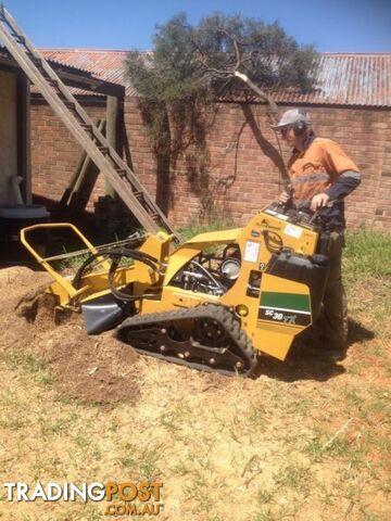
STUMP GRINDING & TREE SERVICES
 Cutting Tools
$1,180$660 more
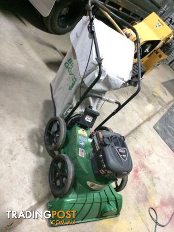
Billy Goat K-Series Vacuum
 Cutting Tools
$28.50$492 less
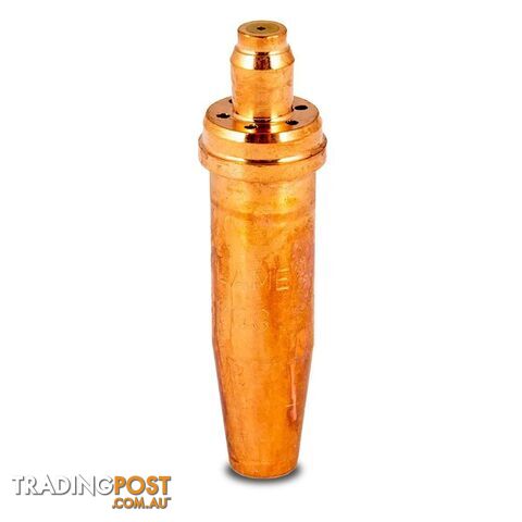
Type 41 Straight Acetylene Gouging Nozzle Unimig U11401
 Cutting Tools
$33.20$487 less
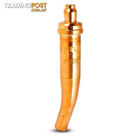
Type 41 Bent Acetylene Gouging Nozzle Unimig U11398
 Cutting Tools
$1,890$1,370 more
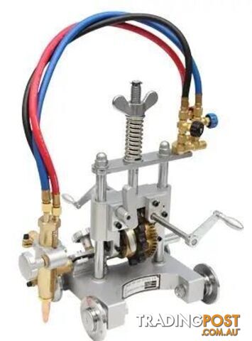
TX-21Q Pipe Cutter w/Quick-Clutch & 2.4m Chain Weldclass 5-TX21Q
 Cutting Tools
$64.95$455 less
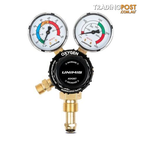
Twin Gauge Oxygen Regulator Unimig U11263
 Cutting Tools
$64.95$455 less
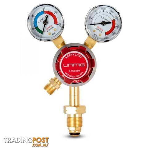
Twin Gauge Acetylene Regulator 0-150 kPa Unimig U11373
 Cutting Tools
$8.60$511 less
Triple Flint Lighter Bulgin 555-00043
 Cutting Tools
$220.15$300 less
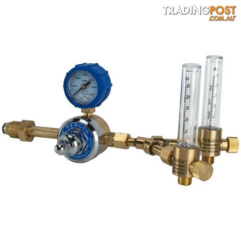
Regulator 1 Stage Side Entry Argon Type 10 Tesuco RC1SAR2FM
 Cutting Tools
$106.95$413 less
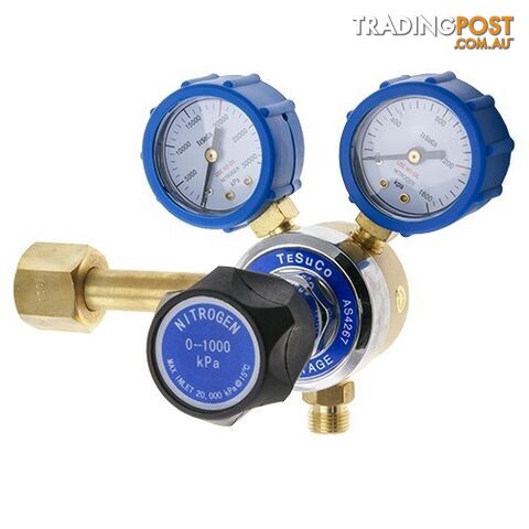
Regulator 1 Stage Side Entry Nitrogen Type 50 Tesuco RC1SNI10

$520
Verified seller
Description
INFLATABLE PURGE SYSTEM 75MM INFLATABLE PURGE DAM TMIPS003Â
Especially insulated heat covered infl atable purge system for purging applications in pre-heated pipes can be supplied upon requested
Made from fi re-retardant âFlameshieldâ proban cotton for increased resistance to
 damage from scorching and burning.
 Armoured, robust connection hose.
 Bypass hose for additional gas inlet/exhaust.
 Reinforced stitching and crimping for improved tear-resistance.
 Strong eyelet pull loops.
 Reduces fl ow rate during hot passes to 5 to 10 lpm.
 Available for pipe diameters from 2â to 96â.
 Special hose barb connections available for easy connection to gas source
OPERATION OF INFLATABLE PURGE SYSTEM
Step 1
The defl ated Purge System can be easily placed in the pipe by using the pull tags.
Step 2
Once the two dams of the Purge System are in position on either side of the weld joint, there is a glowtape in the middle of the dams to advise âin positionâ.
The dams are infl ated by opening the argon source to 5-10 lpm fl ow rate and will quickly seal the pipe.
The pressure will open the purge valve and purging of the space between the pipe and the purge dam begins once dams are infl ated.
During purging, the air between the Purge System and the pipe is pushed through the exhausts of the purge system away from the vicinity of the weld until the oxygen level is low enough to start welding, as per the welding procedure.
Use a purge gas monitor to advise oxygen levels.
The Purge System requires a constant fl ow rate of inert shielding gas of up to 3-5l/min to maintain a positive purge pressure.
Step 3
After completion and the weld has cooled below oxidation temperature the Purge System can be easily defl ated by interrupting the argon gas supply. Once defl ated remove from the pipe.
Note: For best welding results, use infl atable weld purge together with a weld gas analyser
(TMWGA001 or TMSCGA) and aluminium tape to seal the prep areas while purging to reduce gas usage.
Applications
The Purge System can be used whenever welding stainless steel and reactive metal pipework.
Also suitable for purging autogenous weld fi t ups as well as scheduled pipework that requires a gap between two bevelled pipe ends.
Standard Purge Bags: 100°C
Heat Resistant Purge Bags: 350°C continuous - 500°C short term
Part Number/SKU: TMIPS003
* Product Images are for illustration purposes only, unless otherwise specified colour may be different.
Especially insulated heat covered infl atable purge system for purging applications in pre-heated pipes can be supplied upon requested
Made from fi re-retardant âFlameshieldâ proban cotton for increased resistance to
 damage from scorching and burning.
 Armoured, robust connection hose.
 Bypass hose for additional gas inlet/exhaust.
 Reinforced stitching and crimping for improved tear-resistance.
 Strong eyelet pull loops.
 Reduces fl ow rate during hot passes to 5 to 10 lpm.
 Available for pipe diameters from 2â to 96â.
 Special hose barb connections available for easy connection to gas source
OPERATION OF INFLATABLE PURGE SYSTEM
Step 1
The defl ated Purge System can be easily placed in the pipe by using the pull tags.
Step 2
Once the two dams of the Purge System are in position on either side of the weld joint, there is a glowtape in the middle of the dams to advise âin positionâ.
The dams are infl ated by opening the argon source to 5-10 lpm fl ow rate and will quickly seal the pipe.
The pressure will open the purge valve and purging of the space between the pipe and the purge dam begins once dams are infl ated.
During purging, the air between the Purge System and the pipe is pushed through the exhausts of the purge system away from the vicinity of the weld until the oxygen level is low enough to start welding, as per the welding procedure.
Use a purge gas monitor to advise oxygen levels.
The Purge System requires a constant fl ow rate of inert shielding gas of up to 3-5l/min to maintain a positive purge pressure.
Step 3
After completion and the weld has cooled below oxidation temperature the Purge System can be easily defl ated by interrupting the argon gas supply. Once defl ated remove from the pipe.
Note: For best welding results, use infl atable weld purge together with a weld gas analyser
(TMWGA001 or TMSCGA) and aluminium tape to seal the prep areas while purging to reduce gas usage.
Applications
The Purge System can be used whenever welding stainless steel and reactive metal pipework.
Also suitable for purging autogenous weld fi t ups as well as scheduled pipework that requires a gap between two bevelled pipe ends.
Standard Purge Bags: 100°C
Heat Resistant Purge Bags: 350°C continuous - 500°C short term
Part Number/SKU: TMIPS003
* Product Images are for illustration purposes only, unless otherwise specified colour may be different.
Location
Australia
$520

Message seller
About Inflatable Purge System 75mm Inflatable Purge Dam TMIPS003
Report this ad
Tell us what's wrong with this listing.